NDIR CO2 Carbon Dioxide Sensor
-
RK080X series infrared gas sensor. Used in indoor air quality testing, HVAC systems, fresh air equipment, air purification equipment, fans, automatic window control, etc., with good selectivity and stability. It is widely used all over the world.
For the design and manufacture of RK080x series infrared ground sensors, this manual provides important design technical suggestions. Please read this manual carefully before use.
- Overview
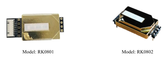
This manual covers our infrared gas sensor RK0801 and RK0802. The design accuracy and size of these models are different. Table 1 summarizes the basic similarities and differences of these models.
RK080x series infrared sensors are designed and manufactured based on Lambert-Beer's law, used to detect target gases, and belong to physical sensors. Not affected by material consumption, the life span is generally longer than that of chemical sensors.
Table 1: Comparison of module models
Model
RK0801
RK0802
size
39.6x 17 x 9(mm)
33 x 17 x 9 (mm)
Design accuracy
±(50ppm+5% reading value)
±(50ppm+5% reading value)
- Technical parameters
- Technical parameters
Table 2: RK080x technical parameters
Model
RK0801
RK0802
measurement range
400~2000ppm (0-1%VOL optional)
working principle
Non-dispersive infrared (NDIR)
Operating Voltage
4.5~5.5V DC
4.5~5.5V DC
Working current
120mA peak
20mA average
120mA peak
20mA average
Precision
±(50ppm+5% reading value)
±(50ppm+5% reading value)
Preheat time
3min
3min
Response time
T90 <120s
T90 <120s
Detection interval
2s
2s
Working conditions
0~50℃/0~90%RH (no condensation)
Storage conditions
-20~60℃/0~90%RH (non-condensing)
Communication Interface
UART level 3.3V
PMW
-
- Interface definition
- Table 3. RK080x interface definition
Pin
name
Features
PIN1、PIN8
CAL
Clean air zero point adjustment input
PIN2、PIN9、PIN12
NC
No connection
PIN3、PIN15
GND
Ground potential
PIN4、PIN16
VDD
Supply voltage
PIN5、PIN11
RXD
UART (RXD) data input
PIN6、PIN10
TXD
UART (TXD) data output
PIN7、PIN13
PWM
Pulse width modulation

- Power supply impact
In order to ensure the normal operation of the sensor, the operating voltage of the sensor is kept in the range of 4.0V~5.5V DC. Exceeding this voltage range may cause malfunction or the sensor cannot work normally.
In order to ensure the normal operation of the sensor, the current output capacity of the power supply should not be less than 150mA. If the power supply current capacity is lower than this value, it may cause a malfunction or the sensor cannot work normally.
4. Interface design
RK080x infrared gas sensor provides multiple output interfaces such as UART and PWM, which can be individually calibrated. It is very convenient to connect the product with the user.
4.1 UART interface
The UART interface is the interface with the most complete functions of this sensor. It is recommended that users use the UART interface. The user-end equipment can read the gas concentration value directly through the sensor's UART interface.(The user terminal needs to use TTL level, if it is RS232 level, please perform level conversion first).The VDD-GND-RXD-TXD of the sensor is connected to the user's 5V-GND-TXD-RXD respectively.
4.1.1 Communication interface settings
If the user uses the UART interface, set the UART communication mode according to the following table.
Table 4. UART settings
Baud rate
9600
Data bit
8-bit
Stop bit
1 bit
Parity bit
no
4.1.2 Communication commands
Table 5. Communication command list
Protocol command interface list and meaning
0x86
Read gas concentration value
0x87
Calibration zero (ZERO)
0x88
Calibration span point (SPAN)
0x79
Turn on/off the automatic zero calibration function
0x86-Read gas concentration value
send command
Byte0
Byte1
Byte2
Byte3
Byte4
Byte5
Byte6
Byte7
Byte8
Start byte
Reserved
command
-
-
-
-
-
Check value
0xFF
0x01
0x86
0x00
0x00
0x00
0x00
0x00
0x79
return value
Byte0
Byte1
Byte2
Byte3
Byte4
Byte5
Byte6
Byte7
Byte8
Start byte
command
8 bits higher in concentration
Concentration lower 8 bits
-
-
-
-
Check value
0xFF
0x86
HIGH
LOW
-
-
-
-
Checksum
Gas concentration value = HIGH * 256 + LOW
0x79-open/close automatic zero calibration
send command
Byte0
Byte1
Byte2
Byte3
Byte4
Byte5
Byte6
Byte7
Byte8
Start byte
Reserved
command
-
-
-
-
-
Check value
0xFF
0x01
0x79
0xA0/0x00
0x00
0x00
0x00
0x00
Checksum
return value
Byte0
Byte1
Byte2
Byte3
Byte4
Byte5
Byte6
Byte7
Byte8
Start byte
command
status
-
-
-
-
-
Check value
0xFF
0x79
0x01/0x00
-
-
-
-
-
Checksum
Note: When Byte3 in the sending command is 0xA0, the automatic calibration function is turned on; when Byte3 is 0x00, the automatic calibration function is turned off. The sensor factory default is to turn on the automatic zero calibration function.
In the return value, Byte2 is the status, 0x01 indicates that the modification is successful, and 0x00 indicates that the modification fails.
0x87-Zero point calibration command
send command
Byte0
Byte1
Byte2
Byte3
Byte4
Byte5
Byte6
Byte7
Byte8
Start byte
Reserved
command
-
-
-
-
-
Check value
0xFF
0x01
0x87
0x00
0x00
0x00
0x00
0x00
Check value
return value
Byte0
Byte1
Byte2
Byte3
Byte4
Byte5
Byte6
Byte7
Byte8
Start byte
command
status
-
-
-
-
-
Check value
0xFF
0x87
0x01/0x00
-
-
-
-
-
Checksum
Note: Byte2 in the return value is the status, 0x01 indicates that the calibration is successful, and 0x00 indicates that the calibration has failed.
The zero point refers to 400ppm. Before sending the zero point calibration command, please make sure that the sensor runs stably at a concentration of 400ppm for more than 20 minutes.
0x88-Calibrate SPAN point command
send command
Byte0
Byte1
Byte2
Byte3
Byte4
Byte5
Byte6
Byte7
Byte8
Start byte
Reserved
command
SPAN high 8 bits
SPAN lower 8 bits
-
-
-
Check value
0xFF
0x01
0x88
HIGH
LOW
0x00
0x00
0x00
Checksum
return value
Byte0
Byte1
Byte2
Byte3
Byte4
Byte5
Byte6
Byte7
Byte8
Start byte
command
status
-
-
-
-
-
Check value
0xFF
0x88
0x01/0x00
-
-
-
-
-
Checksum
Example: If the SPAN value is 2000ppm, then HIGH = 2000/256; LOW = 2000% 256
Note: Byte2 in the return value is the status, 0x01 indicates that the calibration is successful, and 0x00 indicates that the calibration has failed.
Please calibrate the zero point before calibrating the SPAN value.
Before sending the SPAN calibration command, please ensure that the sensor runs stably for more than 20 minutes at the corresponding concentration.
It is recommended to use 2000ppm as the SPAN value for calibration. If you need to use a lower value as the span value, please choose a value above 1000ppm.
4.1.3 Checksum
In order to enhance the reliability of sensor communication, a checksum setting is added to the communication protocol. If the checksum fails, communication is not possible. The specific checksum calculation method is as follows:
Checksum = (Invert (Byte1+Byte2+Byte3+Byte4+Byte5+Byte6+Byte7))+1.
example:
Byte0
Byte1
Byte2
Byte3
Byte4
Byte5
Byte6
Byte7
Byte8
Start byte
Reserved
command
-
-
-
-
-
Check value
0xFF
0x01
0x86
0x00
0x00
0x00
0x00
0x00
Checksum
The calculation is as follows:
- Add from Byte1 to Byte7: 0x01 + 0x86 + 0x00 + 0x00 + 0x00 + 0x00 + 0x00 = 0x87
- Invert: 0xFF-0x87 = 0x78
- Add 1 after inversion: 0x78 + 0x01 = 0x79
C language checksum calculation routine:
C language calculation checksum routine
char getCheckSum(char *packet)
{
char i, checksum;
for( i = 1; i< 8; i++)
{
checksum += packet[i];
}
checksum = 0xff – checksum;
checksum += 1;
return checksum;
}
4.2 PWM interface
RK080x series sensors provide PWM interface, which uses pulse width to characterize target gas concentration. Take a sensor with a measurement range of 2000ppm as an example:
CO2 concentration output range
0~2000ppm
cycle
1004ms±5%
High level output at the beginning of the cycle
2ms (theoretical value)
Middle cycle
1000ms±5%
Low level output at the end of the period
2ms (theoretical value)
The formula for obtaining the current CO2 concentration value through PWM: Cppm=2000×(TH-2ms)/(TH+TL-4ms)
Cppm is the CO2 concentration value obtained by calculation, the unit is ppm
TH is the time when the output is high in an output cycle
TL is the time when the output is low in one output cycle
5.Calibration
RK080x series sensors have two calibration methods: zero point calibration and SPAN point calibration.
5.1 Zero point calibration
In order to facilitate the user to calibrate the zero point, RK080x series sensors have three zero calibration methods: manual zero calibration, command zero calibration and automatic zero calibration. The zero point calibration function refers to calibrating 400ppm.
5.1.1 Manual zero point calibration
Manual zero point calibration is to input a low level (0V) to the CAL pin of the sensor to calibrate the zero point. The low level needs to last for more than 7 seconds. Before calibrating the zero point, make sure that the sensor runs stably for more than 20 minutes at a concentration of 400ppm.
5.1.2 Automatic zero point calibration
The automatic calibration function means that the sensor will intelligently judge the zero point according to the environmental concentration and calibrate itself after a period of continuous operation. The calibration cycle is automatically calibrated once every 26 hours since power-on and operation. The zero point for automatic calibration is 400 ppm.
The automatic zero calibration function is suitable for office environment and home environment. But it is not suitable for agricultural greenhouses, breeding farms, cold storage and other places. In such places, the automatic zero calibration function should be turned off. After closing, the user is required to perform zero point detection on the sensor regularly, and if necessary, command zero calibration or manual zero calibration.
5.1.3 Command zero calibration
Sending calibration commands to the sensor through the serial port (UART) can realize the zero point calibration of the sensor. For the zero point calibration command, please refer to the 0x87-zero point calibration command in the communication.
5.2 SPAN point calibration
Send a calibration command to the sensor through the serial port (UART) to realize the SPAN point calibration of the sensor. For SPAN point calibration command, please refer to 0x88-Calibrate SPAN point command in communication.
- Printed circuit board and shell design
- The influence of the position of the sensor
Infrared sensors are physical sensors and only reflect light inside. Normally, the installation position of the sensor has no effect on the measurement.
-
- Temperature sensor
The infrared sensor is temperature sensitive. In order to accurately measure the ambient temperature around the sensor, the location of the temperature sensor should be as close as possible to the sensor.
-
- Sensor housing design
In order to make the measurement response speed fast enough, the air-permeable part of the sensor housing should be designed to be permeable, and the sensor should be close to the housing opening. It is recommended to use a design with openings on both sides of the housing to improve air flow.
- Packaging design
Infrared sensors are physical sensors that detect gas concentration by light intensity. The physical shape of the sensor may be affected by vibration and pressure during the calculation process, and the sensor measurement may be affected and deviate from the original calibration range. Therefore, it is possible to make shock absorption design in packaging design. Such as adding pearl sponge or foam to the packaging to absorb shock.