Ammonia NH3 sensor with RS485
-
Chapter 1 Product Introduction
-
- Product overview
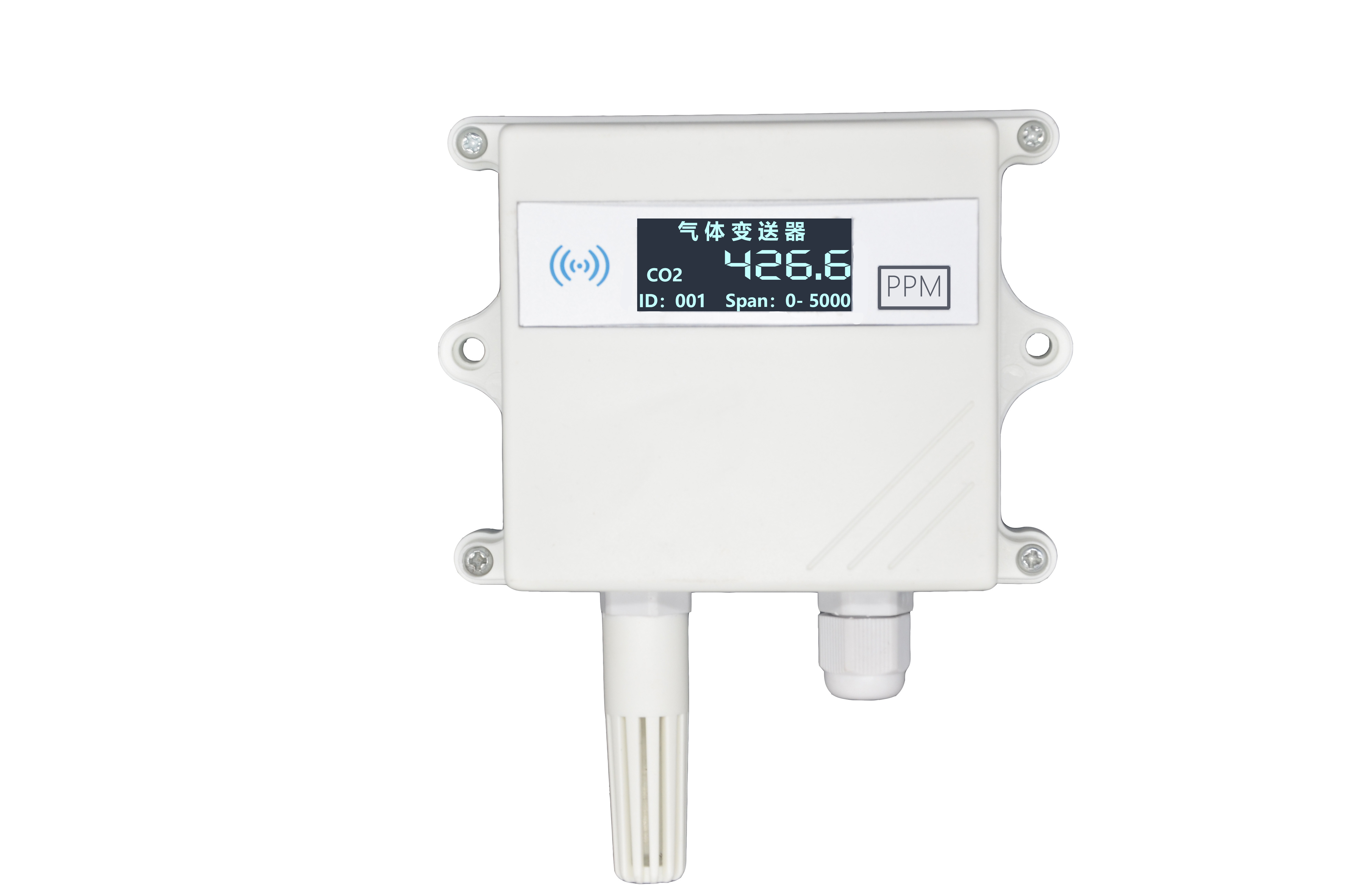
The transmitter is widely used in air quality testing equipment, breeding systems, public toilets and other occasions that require NH3 and temperature and humidity monitoring. The input power supply in the sensor, the sensor probe, and the signal output are completely isolated. It is safe and reliable, beautiful in appearance and easy to install.
The sensor uses more advanced and expensive electrochemical probes, which have higher accuracy and stability than traditional semiconductor probes.
-
- Features
This product adopts high-sensitivity imported semiconductor gas detection probe with stable signal and high precision. It has the characteristics of wide measuring range, good linearity, easy to use, easy to install, and long transmission distance.
-
- The main parameters
Power supply
10~30V DC
Average power consumption
0.18W
output signal
485
Temperature measurement range
-40℃~+80℃
Humidity measurement range
0~100%RH
Temperature accuracy
±0.5℃
Humidity accuracy
±3%RH
NH3 Measuring range
0-500ppm
NH3 Resolution
1ppm
NH3 Precision
±3%FS
Zero drift
±3ppm
Operating temperature
-20~50℃
Working humidity
15~90%RH No condensation
stability
≤2% Signal value/month
Response time
≤30S
Preheat time
≥5 minute
Repeatability
≤2%
Pressure range
90~110Kpa
All the above specifications are measured under environmental conditions: temperature 20℃, relative humidity 50%RH, 1 atmosphere, and the maximum concentration of the gas to be measured does not exceed the sensor range.
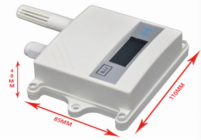
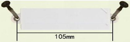
Overall size: 110×85×40mm

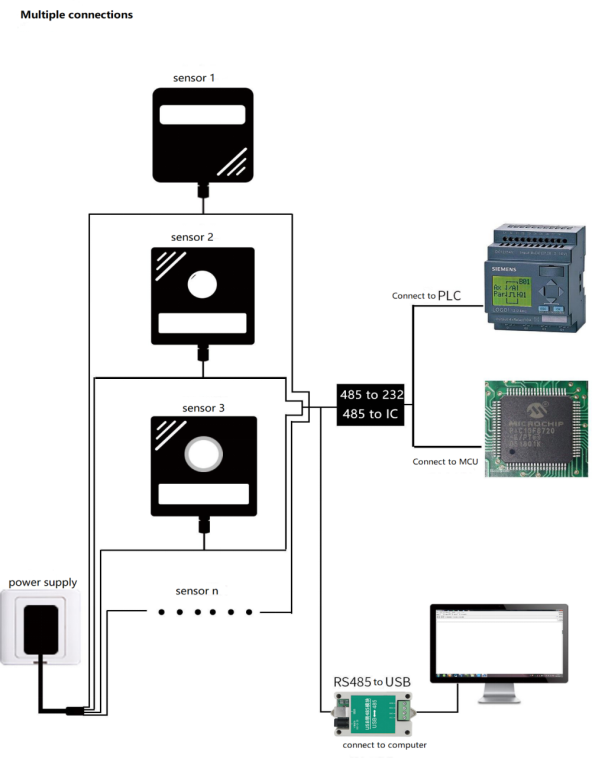
System framework diagram
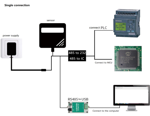

This product can also be combined with multiple sensors on a 485 bus. In theory, one bus can be used for 254 485 sensors, and the other end is connected to a PLC with a 485 interface, and a single-chip microcomputer is connected through a 485 interface chip, or USB to 485 can be used. Computer connection, use the sensor configuration tool provided by our company to configure and test (only one device can be connected when using the configuration software).

-
- Product selection
XK
Company code
102
Wall-mounted king-shaped shell
Wall-mounted king-shaped shell LED display (Ammonia temperature and humidity three-in-one transmitter does not have this model)
NH3-
Ammonia transmitter
NH3WS
Ammonia temperature and humidity integration
N01-
485(Modbus protocol)Output
100P-
Corresponding range 0~100ppm
500P-
Corresponding range 0~500ppm
2
Built-in PE head, select this model for single ammonia gas
4
Built-in hardcover probe, ammonia temperature and humidity integrated default this model
5
Extra hardcover probe, this model is optional for three in one
Chapter 2 Hardware Connection
2.1 Inspection before equipment installation
Equipment List:
■ 1 CO transmitter equipment
■ Self-tapping screws (2 pcs), expansion plugs (2 pcs)
■ Product certificate, warranty card
2.2 Interface description
The power interface is a wide voltage power input, 10-30V can be input. When wiring the 485 signal wire, pay attention to the two wires A and B that cannot be reversed, and the addresses of multiple devices on the bus cannot be conflicted.
2.2.1 Sensor wiring

Thread color
Description
Electricity
source
red
Power is positive(10~30V DC)
black
Power negative
through
letter
yellow
485-A
blue
485-B
**Product warranty for electrochemical probes is one year, probe life is two years, and semiconductor probe life is 3 years
2.3 Installation method

Chapter 3 Configuration Software Installation and Use
Our company provides the supporting "XK test configuration software", which can easily use the computer to read the parameters of the sensor, and flexibly modify the device ID and address of the sensor to complete the firmware upgrade through the serial port (users are not recommended to use this function, only product customization needs Of customers use this feature).
Note that you need to ensure that there is only one sensor on the 485 bus when using the software to obtain it automatically.
3.1 Connect the sensor to the computer
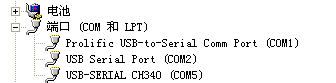
After connecting the sensor to the computer via USB to 485 and supplying power, you can see the correct COM port in the computer (check the COM port in "My Computer—Properties—Device Manager—Port").


Open the data package, select "Debugging Software" --- "485 Parameter Configuration Software", find and open it.
If the COM port is not found in the device manager, it means that you have not installed the USB to 485 driver (included in the data package) or the driver has not been installed correctly, please contact a technician for help.
3.2 Use of sensor monitoring software
①. The configuration interface is shown in the figure. First, obtain the serial port number according to the method in chapter 3.1 and select the correct serial port.
②. Click the test baud rate of the software, the software will test the baud rate and address of the current device, the default baud rate is 9600bit/s, and the default address is 0x01.
③. Modify the address and baud rate according to the needs of use, and at the same time, you can query the current function status of the device.
④. If the test is unsuccessful, please recheck the equipment wiring and 485 driver installation.

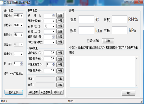
You can click Auto search to automatically search for online devices. At this time, only one device is allowed to be connected to the 485 bus. After the address search is completed, you can use the debugging software to modify the address baud rate. Firmware upgrade.
Chapter 4 Communication Protocol
4.1 Basic communication parameters
Code
8-bit binary
Data bit
8-bit
Parity bit
no
Stop bit
1 person
Error checking
CRC(Redundant cyclic code)
Baud rate
2400bit/s、4800bit/s、9600 bit/s can be set,The factory default is9600bit/s
4.2 Data frame format definition
Using Modbus-RTU communication protocol, the format is as follows:
Initial structure ≥ 4 bytes of time
Address code = 1 byte Function code = 1 byte Data area = N bytes
Error check = 16-bit CRC code
Time to end structure ≥ 4 bytes
Address code: the address of the transmitter, which is unique in the communication network (factory default 0x01).
Function code: The command function instruction issued by the host, this transmitter only uses function code 0x03 (read register data).
Data area: The data area is the specific communication data, pay attention to the high byte of the 16bits data first
CRC code: two-byte check code.
Host query frame structure:
Address
code
function
code
Register start
address
Register
length
Check code
low bit
High bit of
check code
1 byte
1 byte
2 byte
2 byte
1 byte
1 byte
Slave machine response frame structure:
address code
function
code
Number of valid bytes
Data area
Second data area
Nth data area
Check code
1 byte
1 byte
1 byte
2 byte
2 byte
2 byte
2 byte
4.3 Register address
Single NH3 device (other registers are the same, register 0 1 defaults to release ammonia gas concentration compatible with other devices)
Register address
PLC or configuration address
content
operating
Scope and definition
0004 H
40005
NH3 Concentration value
Read only
0~500
Correspond NH3 0-500ppm
NH3 temperature and humidity integrated equipment
Register address
PLC or configuration address
content
operating
Scope and definition
0000 H
40001
Humidity value
Read only
0~1000
(The value after 10 times expansion)
0001 H
40002
Temperature value
Read only
-400~800
(The value after 10 times expansion)
0004 H
40005
NH3 concentration value
Read only
0~1000
Correspond CO 0-1000ppm
006A H
40107
Temperature calibration value
Read and write
10 times larger write
006B H
40108
Humidity calibration value
Read and write
10 times larger write
006C H
40109
NH3 calibration value
Read and write
Actual value write
0064 H
40101
Device address
Read and write
1~255(Factory default 1)
0065H
41002
Device baud rate
Read and write
1 representative 2400
2 representative 4800
3 representative 9600
4.4 Communication protocol example and explanation
4.4.1 Read the CO value of the device address 0x01
Interrogation frame
address
code
function
code
starting
address
Data length
Check code
low bit
High bit of
check code
0x01
0x03
0x00 0x02
0x00 0x01
0x25
0xCA
Reply frame (for example, read that NH3 is 50.0ppm)
address
code
function
code
Returns the
number of valid bytes
NH3 value
Check code
low bit
High bit of
check code
0x01
0x03
0x02
0x01 0xF4
0xBF
0x06
NH3:
1F4 H(Hexadecimal) =500 => NH3=50.0 ppm
4.4.2 Read the temperature, humidity and NH3 value of the device address 0x01
Inquiry frame 000000-Tx: 01 03 00 00 00 04 44 09
address
code
function
code
starting
address
Data length
Check code low bit
High bit of
check code
0x01
0x03
0x00 0x00
0x00 0x04
0x44
0x09
Response frame (for example, temperature value -7.5℃, humidity value 35.9%, NH3 value 500ppm)
address
code
function
code
Number of
bytes
Humidity
value
Temperature
value
Air
pressure
NH3
CRCL
CRCH
0x01
0x03
0x08
0x01 0x67
0xFF 0xB5
0x00 0x00
0x01 0xF4
0x34
0x89
Reserved air pressure register
Temperature: When the temperature is lower than 0℃, upload in the form of complement code.
FFB5 H (hexadecimal) = -75 => temperature = -7.5℃
humidity: 167 H (hexadecimal) = 359 => humidity = 35.9%RH
NH3:1F4 H(hexadecimal) =500 => CO=500 ppm
4.5 Conversion relationship between NH3 measurement unit ppm and ug/m3
The conversion formula is based on 25°C and 1 atmosphere: X ppm = (Y mg/m3)(24.45)/(molecular weight) or Y mg/m3 = (X ppm)(molecular weight)/24.45
Only suitable for calculating NH3: 1ppm=1.15mg/m3 1mg/m3=0.87ppm
Chapter 5 Common Problems and Solutions
No output or output error
possible reason:
- The computer has a COM port, and the selected port is incorrect.
- The baud rate is wrong.
- The 485 bus is disconnected, or the A and B wires are reversed.
- If the number of equipment is too much or the wiring is too long, power supply should be nearby, add 485 booster, and add 120Ω terminal resistance.
- The USB to 485 driver is not installed or damaged.
- Equipment damage.
Chapter 1 Product Introduction
-
- Product overview
The transmitter is widely used in air quality testing equipment, breeding systems, public toilets and other occasions that require NH3 and temperature and humidity monitoring. The input power supply in the sensor, the sensor probe, and the signal output are completely isolated. It is safe and reliable, beautiful in appearance and easy to install.
The sensor uses more advanced and expensive electrochemical probes, which have higher accuracy and stability than traditional semiconductor probes.
-
- Features
This product adopts high-sensitivity imported semiconductor gas detection probe with stable signal and high precision. It has the characteristics of wide measuring range, good linearity, easy to use, easy to install, and long transmission distance.
-
- The main parameters
Power supply
10~30V DC
Average power consumption
0.18W
output signal
485
Temperature measurement range
-40℃~+80℃
Humidity measurement range
0~100%RH
Temperature accuracy
±0.5℃
Humidity accuracy
±3%RH
NH3 Measuring range
0-500ppm
NH3 Resolution
1ppm
NH3 Precision
±3%FS
Zero drift
±3ppm
Operating temperature
-20~50℃
Working humidity
15~90%RH No condensation
stability
≤2% Signal value/month
Response time
≤30S
Preheat time
≥5 minute
Repeatability
≤2%
Pressure range
90~110Kpa
All the above specifications are measured under environmental conditions: temperature 20℃, relative humidity 50%RH, 1 atmosphere, and the maximum concentration of the gas to be measured does not exceed the sensor range.
Overall size: 110×85×40mm
-
- System framework diagram
This product can also be combined with multiple sensors on a 485 bus. In theory, one bus can be used for 254 485 sensors, and the other end is connected to a PLC with a 485 interface, and a single-chip microcomputer is connected through a 485 interface chip, or USB to 485 can be used. Computer connection, use the sensor configuration tool provided by our company to configure and test (only one device can be connected when using the configuration software).
-
- Product selection
XK
Company code
102
Wall-mounted king-shaped shell
Wall-mounted king-shaped shell LED display (Ammonia temperature and humidity three-in-one transmitter does not have this model)
NH3-
Ammonia transmitter
NH3WS
Ammonia temperature and humidity integration
N01-
485(Modbus protocol)Output
100P-
Corresponding range 0~100ppm
500P-
Corresponding range 0~500ppm
2
Built-in PE head, select this model for single ammonia gas
4
Built-in hardcover probe, ammonia temperature and humidity integrated default this model
5
Extra hardcover probe, this model is optional for three in one
Chapter 2 Hardware Connection
2.1 Inspection before equipment installation
Equipment List:
■ 1 CO transmitter equipment
■ Self-tapping screws (2 pcs), expansion plugs (2 pcs)
■ Product certificate, warranty card
2.2 Interface description
The power interface is a wide voltage power input, 10-30V can be input. When wiring the 485 signal wire, pay attention to the two wires A and B that cannot be reversed, and the addresses of multiple devices on the bus cannot be conflicted.
2.2.1 Sensor wiring
Thread color
Description
Electricity
source
red
Power is positive(10~30V DC)
black
Power negative
through
letter
yellow
485-A
blue
485-B
**Product warranty for electrochemical probes is one year, probe life is two years, and semiconductor probe life is 3 years
2.3 Installation method
Chapter 3 Configuration Software Installation and Use
Our company provides the supporting "XK test configuration software", which can easily use the computer to read the parameters of the sensor, and flexibly modify the device ID and address of the sensor to complete the firmware upgrade through the serial port (users are not recommended to use this function, only product customization needs Of customers use this feature).
Note that you need to ensure that there is only one sensor on the 485 bus when using the software to obtain it automatically.
3.1 Connect the sensor to the computer
After connecting the sensor to the computer via USB to 485 and supplying power, you can see the correct COM port in the computer (check the COM port in "My Computer—Properties—Device Manager—Port").
Open the data package, select "Debugging Software" --- "485 Parameter Configuration Software", find and open it.
If the COM port is not found in the device manager, it means that you have not installed the USB to 485 driver (included in the data package) or the driver has not been installed correctly, please contact a technician for help.
3.2 Use of sensor monitoring software
①. The configuration interface is shown in the figure. First, obtain the serial port number according to the method in chapter 3.1 and select the correct serial port.
②. Click the test baud rate of the software, the software will test the baud rate and address of the current device, the default baud rate is 9600bit/s, and the default address is 0x01.
③. Modify the address and baud rate according to the needs of use, and at the same time, you can query the current function status of the device.
④. If the test is unsuccessful, please recheck the equipment wiring and 485 driver installation.
You can click Auto search to automatically search for online devices. At this time, only one device is allowed to be connected to the 485 bus. After the address search is completed, you can use the debugging software to modify the address baud rate. Firmware upgrade.
Chapter 4 Communication Protocol
4.1 Basic communication parameters
Code
8-bit binary
Data bit
8-bit
Parity bit
no
Stop bit
1 person
Error checking
CRC(Redundant cyclic code)
Baud rate
2400bit/s、4800bit/s、9600 bit/s can be set,The factory default is9600bit/s
4.2 Data frame format definition
Using Modbus-RTU communication protocol, the format is as follows:
Initial structure ≥ 4 bytes of time
Address code = 1 byte Function code = 1 byte Data area = N bytes
Error check = 16-bit CRC code
Time to end structure ≥ 4 bytes
Address code: the address of the transmitter, which is unique in the communication network (factory default 0x01).
Function code: The command function instruction issued by the host, this transmitter only uses function code 0x03 (read register data).
Data area: The data area is the specific communication data, pay attention to the high byte of the 16bits data first
CRC code: two-byte check code.
Host query frame structure:
Address
code
function
code
Register start
address
Register
length
Check code
low bit
High bit of
check code
1 byte
1 byte
2 byte
2 byte
1 byte
1 byte
Slave machine response frame structure:
address code
function
code
Number of valid bytes
Data area
Second data area
Nth data area
Check code
1 byte
1 byte
1 byte
2 byte
2 byte
2 byte
2 byte
4.3 Register address
Single NH3 device (other registers are the same, register 0 1 defaults to release ammonia gas concentration compatible with other devices)
Register address
PLC or configuration address
content
operating
Scope and definition
0004 H
40005
NH3 Concentration value
Read only
0~500
Correspond NH3 0-500ppm
NH3 temperature and humidity integrated equipment
Register address
PLC or configuration address
content
operating
Scope and definition
0000 H
40001
Humidity value
Read only
0~1000
(The value after 10 times expansion)
0001 H
40002
Temperature value
Read only
-400~800
(The value after 10 times expansion)
0004 H
40005
NH3 concentration value
Read only
0~1000
Correspond CO 0-1000ppm
006A H
40107
Temperature calibration value
Read and write
10 times larger write
006B H
40108
Humidity calibration value
Read and write
10 times larger write
006C H
40109
NH3 calibration value
Read and write
Actual value write
0064 H
40101
Device address
Read and write
1~255(Factory default 1)
0065H
41002
Device baud rate
Read and write
1 representative 2400
2 representative 4800
3 representative 9600
4.4 Communication protocol example and explanation
4.4.1 Read the CO value of the device address 0x01
Interrogation frame
address
code
function
code
starting
address
Data length
Check code
low bit
High bit of
check code
0x01
0x03
0x00 0x02
0x00 0x01
0x25
0xCA
Reply frame (for example, read that NH3 is 50.0ppm)
address
code
function
code
Returns the
number of valid bytes
NH3 value
Check code
low bit
High bit of
check code
0x01
0x03
0x02
0x01 0xF4
0xBF
0x06
NH3:
1F4 H(Hexadecimal) =500 => NH3=50.0 ppm
4.4.2 Read the temperature, humidity and NH3 value of the device address 0x01
Inquiry frame 000000-Tx: 01 03 00 00 00 04 44 09
address
code
function
code
starting
address
Data length
Check code low bit
High bit of
check code
0x01
0x03
0x00 0x00
0x00 0x04
0x44
0x09
Response frame (for example, temperature value -7.5℃, humidity value 35.9%, NH3 value 500ppm)
address
code
function
code
Number of
bytes
Humidity
value
Temperature
value
Air
pressure
NH3
CRCL
CRCH
0x01
0x03
0x08
0x01 0x67
0xFF 0xB5
0x00 0x00
0x01 0xF4
0x34
0x89
Reserved air pressure register
Temperature: When the temperature is lower than 0℃, upload in the form of complement code.
FFB5 H (hexadecimal) = -75 => temperature = -7.5℃
humidity: 167 H (hexadecimal) = 359 => humidity = 35.9%RH
NH3:1F4 H(hexadecimal) =500 => CO=500 ppm
4.5 Conversion relationship between NH3 measurement unit ppm and ug/m3
The conversion formula is based on 25°C and 1 atmosphere: X ppm = (Y mg/m3)(24.45)/(molecular weight) or Y mg/m3 = (X ppm)(molecular weight)/24.45
Only suitable for calculating NH3: 1ppm=1.15mg/m3 1mg/m3=0.87ppm
Chapter 5 Common Problems and Solutions
No output or output error
possible reason:
- The computer has a COM port, and the selected port is incorrect.
- The baud rate is wrong.
- The 485 bus is disconnected, or the A and B wires are reversed.
- If the number of equipment is too much or the wiring is too long, power supply should be nearby, add 485 booster, and add 120Ω terminal resistance.
- The USB to 485 driver is not installed or damaged.
- Equipment damage.
-